
LEDs now dominate lighting across applications from simple indicator lights to large-scale video walls used in broadcast studios, houses of worship, and event venues. DIYers, AV integrators, facilities managers, and technicians all work with LED circuits — and all of them run into the same beginner friction: misreading a wiring diagram or skipping a calculation step.
This guide covers how to read LED wiring diagrams, understand series versus parallel circuit logic, and wire correctly from the start. No theoretical fluff — just what you actually need to know before touching a wire.
Key Takeaways
- LED wiring diagrams use standardized symbols — learn them before starting any physical wiring
- Series circuits keep current consistent; parallel circuits keep voltage consistent — choose based on your supply voltage and LED count
- Calculate resistor value first: R = (Vs − Vf) ÷ If — do this before any physical wiring
- Polarity matters every time: reversed anode and cathode connections prevent operation and can shorten LED lifespan
- Large-scale or permanent LED display installations require certified engineering support, not DIY assembly
Reading an LED Wiring Diagram: Symbols and Notation Explained
An LED wiring diagram — or schematic — is a standardized visual map of how components connect electrically. It uses universal symbols rather than pictures of actual parts. As DigiKey explains, these symbols follow established conventions so any trained reader can interpret the same drawing regardless of brand or country.
Core Symbols You'll Encounter
| Symbol | What It Represents |
|---|---|
| LED | Diode symbol with two outward-pointing arrows indicating light emission; anode (A/+) is the positive leg, cathode (C/−) is negative |
| Resistor | Zigzag line (ANSI/American standard) or rectangular block (IEC/international standard) |
| DC Power Source | Unequal parallel lines for a single cell; repeated pairs for a battery |
| SPST Switch | One pole, one throw — simple on/off |
| SPDT Switch | One common pole switchable between two throws — routes between two circuits |
Polarity on physical LEDs: On standard 5mm LEDs, the longer lead is the anode (+) and the shorter lead is the cathode (−). On LED strip pads, polarity is typically marked directly.
The Limiting Resistor — Why It's Non-Negotiable
LEDs have no built-in resistance. Without a current-limiting resistor, they draw whatever current the supply can deliver — which causes immediate or latent failure.
The formula is:
R = (Vs − Vf) ÷ If
- Vs = supply voltage
- Vf = LED forward voltage (from the datasheet)
- If = desired forward current in amperes (from the datasheet)
Always use worst-case datasheet values — they give you the safety margin that keeps your LED from burning out prematurely.
Schematic vs. Physical Wiring Diagram
These are not the same document:
- Schematic: Shows logical electrical connections using standardized symbols — no indication of physical layout or component placement
- Physical/pictorial diagram: Shows real components and their actual routing and placement
Beginners frequently mix these up. Used together, they give you the full picture: the schematic defines the electrical logic, and the physical diagram shows you how to translate that logic into actual wire runs and component positions.
Series vs. Parallel: Choosing the Right LED Circuit
Three configurations cover most LED wiring scenarios: series, parallel, and series/parallel hybrid. Which one you use depends on your supply voltage, your LED count, and whether current consistency or voltage flexibility matters more for your application.
Series Circuits
In a series circuit, the anode of each LED connects to the cathode of the next (a daisy chain). The same current flows through every LED in the string.
Key rules:
- Total required voltage = sum of all LED forward voltages
- One current-limiting resistor can control the entire string
- If one LED fails, the entire string goes dark
Example: Three LEDs with a 3.2V forward voltage each require at least 9.6V from the supply before accounting for the resistor's voltage drop.
As documented by All About Circuits, series wiring enforces identical current through every component in the loop. That predictability is what makes it the go-to starting point before considering parallel configurations.
Parallel Circuits
Series circuits work cleanly when voltage headroom allows — but parallel wiring becomes necessary when you need to run multiple LEDs at lower voltages. In a parallel circuit, all anodes connect to a shared positive rail and all cathodes to a shared negative rail. Each LED sees the same voltage, but total current draw equals the sum of all individual LED currents.
The critical risk: LEDs from the same batch can still have different forward voltage (Vf) characteristics. Texas Instruments documents that small Vf differences cause unequal current sharing across parallel branches. The lower-Vf path draws more current, runs hotter, and can enter thermal runaway.
Thermal runaway is a feedback loop: higher temperature allows more current, which creates more heat, which allows even more current — a cycle that continues until the LED fails.
To manage this: each parallel branch needs its own ballast resistor. A single shared resistor cannot guarantee equal current distribution across unmatched parallel LEDs.
Series/Parallel Hybrid
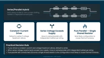
When the sum of forward voltages in a full series string exceeds your driver's output range, divide the LEDs into multiple series strings and connect those strings in parallel. Each string still needs its own current-limiting resistor or regulated current path.
Practical decision rule:
- If your driver is constant-current and voltage headroom allows, default to series
- When series voltage requirements exceed your supply, move to series/parallel with independent ballast per string
- Pure parallel with unmatched LEDs and a single shared resistor is the configuration most likely to cause thermal runaway
What You Need Before Wiring LEDs
Confirm each of these before picking up a soldering iron.
LED Specifications
Pull the datasheet for your specific LED. You need:
- Vf (forward voltage): the voltage drop across the LED at operating current
- If (forward current): the target operating current in milliamps
Without both values, the resistor calculation is impossible.
Power Source
Determine whether your circuit needs a constant-current or constant-voltage driver:
- Raw LEDs and series strings are current-driven, so use a constant-current driver
- LED strips with onboard current limiting use a matching constant-voltage supply
Match the driver to what the LED or strip datasheet specifies, not to appearance or assumed convention.
Wire Gauge
Wire must handle the total current load without overheating. As a reference point, NEC Table 402.5 lists ampacity values for copper fixture wire:
| Wire Gauge | Table 402.5 Ampacity |
|---|---|
| 18 AWG | 6 A |
| 16 AWG | 8 A |
| 14 AWG | 17 A |
| 12 AWG | 23 A |
Important: These values apply to fixture wire under specific conditions. Run length, insulation type, temperature, and installation method all affect the correct wire selection. Use these as a starting reference, then verify against the actual conditions of your installation.
Tools
- Soldering iron or solderless connectors
- Multimeter (non-negotiable): verify polarity and voltage before powering on
- Heat shrink tubing or electrical tape for insulation
How to Wire LEDs: A Step-by-Step Walkthrough
Skipping steps — especially calculation and polarity verification — is the primary cause of failed circuits. Follow this sequence.
Setup and Planning
1. Calculate your limiting resistor
Using R = (Vs − Vf) ÷ If, confirm the resistor value for your specific supply voltage and LED specs. For multiple LEDs in series, use the summed forward voltage: R = (Vs − sum of all Vf) ÷ If.
2. Size your power supply
(Watts per LED × Quantity) + 10% buffer = minimum power supply wattage
The 10% buffer accounts for efficiency losses and prevents running the supply at its absolute maximum.
3. Draw or reference your wiring diagram
Mark positive and negative paths clearly before touching any wire. Polarity errors during assembly almost always happen when the diagram is skipped.
Wiring the Circuit
For a series circuit, follow this path:
- Positive supply terminal → switch → resistor → LED anode
- LED cathode → next LED anode (repeat for additional LEDs)
- Final LED cathode → negative supply terminal
This forms a complete loop. The current is the same at every point.
For parallel circuits:
- Wire a common positive rail and a common negative rail
- Each LED (or LED/resistor pair) bridges between the two rails
- Each branch requires its own resistor. One shared resistor before the parallel junction does not control individual branch currents
Verifying Before Power-On
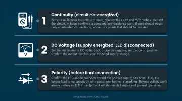
Run these three checks in order before applying power:
Continuity (circuit de-energized): Set your multimeter to continuity mode, connect the COM and V/Ω probes, and test the circuit. A beep confirms a complete low-resistance path. Beeps should occur only at intended connections, not across points that should be isolated.
DC voltage (supply energized, LED disconnected): Set the multimeter to DC volts, black probe on negative, red probe on positive. Confirm the output matches your expected supply voltage.
Polarity (before final connection): Confirm the LED anode connects toward the positive supply. On 5mm LEDs, the longer lead is the anode; on strip pads, look for the "+" marking. Reverse polarity won't always destroy an LED instantly, but it will shorten its lifespan and prevent operation.
Common LED Wiring Mistakes to Avoid
- Connecting LEDs without a current-limiting resistor leads to electrical overstress — either immediate failure or latent degradation hours later, per Cree's electrical overstress documentation
- Reversed polarity prevents the LED from lighting and gradually degrades the device with each exposure
- An undersized power supply running at or beyond its rated output causes voltage drop, producing dim or flickering LEDs and shortening the supply's lifespan
- Mixing LEDs with different forward voltage (Vf) values in parallel: even small Vf differences create large current imbalances across branches, pushing the lower-Vf branch toward thermal runaway first
These mistakes matter most at the component level. Scale up to a permanent video wall installation — in an event venue, house of worship, or broadcast studio — and the engineering scope expands considerably: multi-panel power distribution, signal processing hardware, and load calculations all require careful planning before anything powers on. That's where working with NovaStar-certified LED engineers, like the team at CMG Visuals, makes a measurable difference in how the system performs and holds up over time.
Frequently Asked Questions
What is the difference between wiring LEDs in series vs. in parallel?
In series wiring, all LEDs share one current path: current stays equal throughout, and voltage requirements add up across the string. In parallel wiring, each LED gets its own branch from a shared supply, so voltage stays equal per LED while total current adds up. Series works well with constant-current drivers; parallel suits fixed-voltage supplies with higher LED counts.
Do I need a resistor for every LED I wire?
In a parallel circuit, yes — each branch needs its own resistor to control its individual current. In a series circuit, one resistor typically manages the entire string since current is common throughout. Omitting a resistor entirely causes electrical overstress regardless of circuit type.
What wire gauge should I use for LED wiring?
Wire gauge depends on total current load — lower AWG numbers carry more current. NEC Table 402.5 lists 18 AWG at 6 A for fixture wire as a reference point, but correct selection also depends on run length, insulation rating, and installation conditions. Size up when in doubt.
How can I tell if I wired my LED correctly before powering on?
Run a continuity test with your multimeter to check for shorts, then verify the LED's anode connects toward the positive supply terminal. Follow up with a DC voltage check at the supply output before applying power to the full circuit.
What is the difference between addressable and non-addressable LED wiring?
Non-addressable LEDs share a single circuit, so all LEDs respond identically to one control signal. Addressable LEDs (such as WS2812B-family devices) integrate an LED and a control chip per pixel, requiring power, ground, and a data signal line that chains from pixel to pixel for individual control.
When should I hire a professional instead of wiring LEDs myself?
DIY wiring is appropriate for simple, low-voltage projects where total current is modest and the installation is non-permanent. Permanent installations, high-power arrays, and commercial display systems — including video walls — require certified engineering expertise to meet safety standards and ensure code compliance. Teams like CMG Visuals' NovaStar-certified engineers handle this level of complexity for corporate, event, and broadcast environments.